Republic Sniper is a futuristic first-person shooter game for mobile devices, so we wanted the ability to disintegrate and dissolve enemies in interesting ways. While you start the game with ballistic firearms not so very different from the guns used today, as you progress through the game, you earn more advanced and better weaponry. For the spiffy futuristic weapons you get later in the game, having the bad guys simply fall down seemed a little… mundane.
To come up with more interesting ways for our virtual baddies to die, I started experimenting with Unreal Engine 4’s material system. The end result of my experimentation was a good general purpose method of dissolving, disintegrating, and dispersing objects.
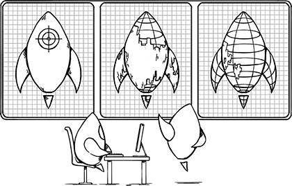
This post will walk through the process of creating and using this dissolve material, which can be configured to create many variations on the same basic effect, such as this:

The Basic Approach
We’ll use a grayscale image to drive the disintegration. Using an image gives us a great deal of flexibility and control and lets us modify the overall look of the effect by simply changing a single texture parameter.
For testing purposes, I chose a simple gradient texture. This one, in fact:

This image won’t result in the most interesting effect, but it will be easy to see the impact of changes we make to our material. Once we’re done, we can swap in other textures. With this material, you’ll be able to get surprisingly interesting variations simply by playing with different filters in Photoshop and saving the results to an image file.
The image will be mapped to 3D objects the same way that a regular texture map is, only instead of being used for the color of the object, it will control how the object dissolves. Remember, digital images are just two dimensional arrays of numbers represented visually. Black pixels are 0.0, white pixels are 1.0 and the various shades of gray represent values between 0.0 and 1.0. By “wrapping” a grayscale image around an object, every point on the surface of the object ends up with a corresponding value between 0.0 and 1.0 that can be accessed from our material.
How does that help us? Our material will have an additional parameter we can set from Blueprint or C++ to represent just how dissolved the object is. If we set it to 0.0, the object will be completely intact. If we set it to 1.0, the object will be completely dissolved. If we set it to any value in between, it will represent a partial state of disintegration.
Our material will look at the values from the grayscale image. If the value pulled from the image texture for the pixel being drawn is less than the current dissolve value, we’ll mask that part of the object, making it transparent. If the value is above the dissolve parameter, we’ll draw the pixel normally. By incrementing the dissolve parameter from 0.0 to 1.0 over a short period of time, our object will go from completely opaque to completely transparent, making it appear to disintegrate.
Getting Started
Whenever I’m working on anything that’s experimental and I don’t know if the end result will make it into the final game, I like to work in a new, blank project. When I’m all done, if I’m happy with the result, I can migrate the assets over to the official game project, but if I’m unhappy with the result, all those assets stay in the original project. This helps keep the main project from becoming too cluttered with the detritus of failed experiments.
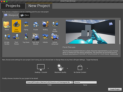
In this particular case, I chose the standard First Person project template. It really doesn’t matter which template you use, but the First Person template seemed a good choice because it’s easy to navigate around and there’s no character or pawn to get between the camera and the things being dissolved. I also thought it would be more fun to shoot things and make them dissolve. Why write a game if you’re not going to have fun in the process, right?
If you want to follow along at home, the new project settings I used can be seen below. If you don’t want to follow along and just want to download the completed material, you can find the sample project here.
Once your new project opens, create a new folder called “DissolveMaterial” and import the texture you want to use by clicking the Import button at the top of the Content Browser. Once UE4 finishes importing, double-click the newly created texture file to bring up the Texture Editor. There’s one important setting in here that we have to change.
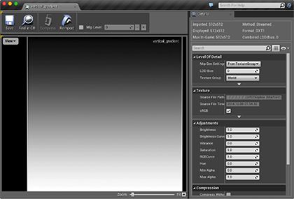
On the right side of the editor, in the Details Inspector, look for the subheading Texture, and find a checkbox labeled sRGB. With most textures, this will default to checked. When this is clicked, UE4 will gamma correct the image. Generally, you want this for color maps, but not when you’re using an image to hold other data, the way we are here. Base color (or “diffuse” maps) should have this checked but gloss maps, bump maps, normal maps, and the like generally should not. Uncheck sRGB so it leaves the image unmodified. You should make sure to do this with any image you import for use with this technique.
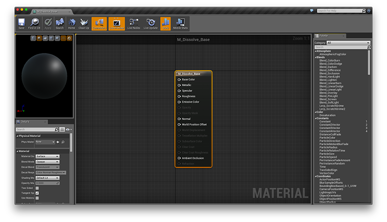
The next step is to create a new material by selecting Material from the Create button menu. Once the new material has been created, rename it “M_Dissolve_Base”. We use “M_Dissolve_Base” rather than just “M_Dissolve” because we’ll later be creating both dynamic and static material instances from this base material. The name is a reminder that we should never actually use the “M_Dissolve_Base” material directly.
Double-clicking the new material will bring up the UE4 Material Editor.
Setting up the Material for Transparency
The first thing we need to do with this new material is to change its Blend Mode to enable transparency. Newly created materials default to a blend mode of Opaque, which won’t work. If the material node is not selected, single-click it to select it. In the lower-left, look for Blend Mode in the Details inspector.
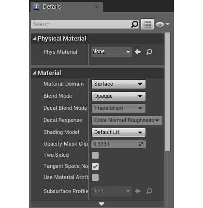
There are two blend modes that could potentially work for us here: Masked and Translucent. The main difference between these two options is that with Masked, any pixel must be either fully transparent or fully opaque, but with Translucent, pixels can be partially transparent. Either option could be made to work for a dissolve material, but I chose Masked because the calculations are easier and the performance will be better. For the types of short disintegrations I’m planning to use this material for, the impact of partially transparent pixels would barely be discernible. Additionally, since Republic Sniper is a mobile game, I thought it made sense to start with the less GPU-intensive of the two options.
After setting the Blend Mode to Masked, drag the texture vertical_gradient from the Content Browser to the node graph of the new material. This will add a Texture Sample node to the graph based on the image.
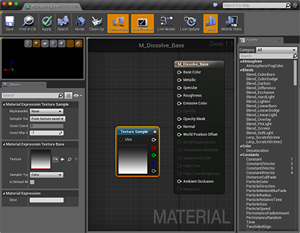
Even though the image we imported was a grayscale image, UE4 has created an RGBA texture sample node with five output pins. That’s okay. We’ll leave the sampler type as Color, but we’ll just use the Red channel to drive our calculations.
To get a preview of how this texture will be applied to an object, click and drag from the top white pin of the texture node to the Base Color pin of the material node. Once it’s connected, we should be able to see how the texture will be applied. In this case, I’m just previewing with the primitive shapes available in the editor, but when working with real assets, you can use the Teapot icon to preview with any mesh asset that you’ve selected in the Content Browser to see how the texture will map to your actual game assets.
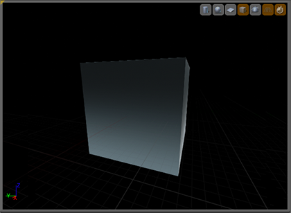
This preview tells us how the object will dissolve with this texture. With the cube above, we can see that the dissolve will start at the top, where the pixels are black, and will work its way down toward the white pixels at the bottom.
Break the link between the two nodes by right-clicking on the Base Color pin and selecting Break Link(s). We connected them just to help visualize how the texture will be applied to a 3D object.
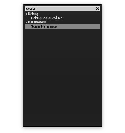
Somewhere in the node graph, right-click. This will bring up a menu. When it comes up, type “scalar”. The list of options should narrow down to just a couple items. Select ScalarParameter from the remaining items. That will create a new node and make the node’s name editable. Type “Dissolve Amount” to name the parameter.
A Scalar Parameter on a Material is a single value (as opposed to a Vector Parameter that holds multiple values, such as x, y, and z coordinates) that can be changed in a material instance created from this material. Parameters let us create new variations of the material from the same node graph by creating static material instances. They also let us change material values at runtime by creating dynamic material instances. This particular parameter is the one that we will change over time to make objects dissolve.
In the Details pane, you’ll see a default value of 0, which is actually what we want since objects will generally start intact. You can change this value while working on your material to preview the effect, but you’ll want to make sure you set it back to 0 when you’re done. There’s also an option called Group. That option lets you group parameters together in the Material Instance Editor detail view. Type “Dissolve” there to place this parameter in a group called “Dissolve”. We’ll use this same value for all of our parameters so that they get grouped together in the inspector.
Right-click on the Texture Sample node and select Convert to Parameter. When prompted for a name, type “Dissolve Texture”. Assign a Group of Dissolve to this one also. Now that our texture is a parameter, we’ll be able to assign different images to this texture when we create instances based on it.
Before we start hooking nodes up, let’s add just a couple more nodes. These nodes will only be used while we’re developing the material and will be deleted before we’re done. Right-click and type “Time”. Add a Time node. This node is a built-in input that changes with the passage of time. Right-click again and type “Sine” and select a Sine node. Click on the output pin of the Time node and drag it out to the input pin of the Sine node. Now, drag the output of the Sine node out, and when prompted type “abs” and create an Abs (for “absolute value”) node.
What we’re doing here is getting the sine value of the elapsed time. Why? Because Sine returns values between -1.0 and 1.0, so the absolute value of a Sine result will always be in the range 0.0 to 1.0, just like our dissolve parameter. That means this will give us a constantly changing value between 0.0 and 1.0. If we use the output of the Abs node instead of the Dissolve Amount parameter node to drive the effect while developing, our material will constantly animate back and forth in the preview pane so we can get an approximation of how our dissolve effect will look at runtime. Later, when we’re happy with the look, we can simply disconnect the Time, Sine, and Abs nodes and connect the Dissolve Amount parameter in their stead.
Optionally, if you want to slow down the speed of the preview animation, you can add a Divide node between the Time and Sine nodes. The larger the number you set for ConstB in the Divide node, the more you’ll slow down the animation.
This is what our node setup should look like now:
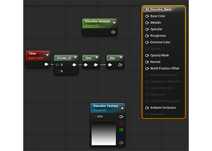
The preview won’t show anything yet, because nothing is hooked up to our material node. Let’s rectify that.
Getting the Basic Dissolve Value
Because, a Masked material only allows fully transparent or fully opaque pixels, we need to provide a value of either 1.0 or 0.0 to the Opacity Mask. Our node graph has to generate 1.0 or 0.0 for every pixel being drawn. To do that, we’ll use an If node to compare the pixel value pulled from Dissolve Texture with the value of Dissolve Amount. We’ll output 0.0 or 1.0 depending on that comparison. Right-click on the node graph and type “If” to create an If node.
If you’re new to node-based materials, you might be wondering how we can compare a texture to a number. Well, the answer is that this comparison will actually happen many times. For every frame this comparison will happen once per pixel potentially affected by the drawing of this object. It will pull one pixel from the texture map based on the screen pixel being drawn and compare that to the Dissolve Amount value.
For starters, we’re not going to use the Dissolve Amount parameter, though, we’re going to use the output of the Abs node. So, click and drag from the Abs node output pin to the A pin of the If node. Next, connect the red pin of the Dissolve Texture node to the B pin of the If node.
Now, hold down the 1 key on your keyboard and left-click somewhere in the node graph. This is a shortcut for adding scalar constants to your node graph. We just added a constant node representing the number 0. Repeat to add a second 0 node, but after creating it, select the second 0 node by left-clicking on it. In the Details pane, change the node’s value to 1.0.
Connect the 0 node to the A>=B pin of the If node and connect the 1 node to the A<B pin and the A==B pin of the If node.
Finally, drag from the output pin of the If node to the Opacity Mask pin of your material.
When you’re using If nodes, the A==B pin is actually optional, which you can tell by the fact that when it’s not connected, it’s a slightly lighter shade of gray than the other input pins. If you use the A==B pin, the A>=B pin actually becomes an A>B pin, but its label doesn’t change to reflect that.
You now have a material that constantly disappears and reappears. You probably can’t see it very well, though, because our material has no color, meaning it defaults to black. To fix that, let’s provide a Base Color for our material. Hold down the 3 key on your keyboard and click on the node graph. That’s a shortcut for adding a three-component vector constant to your material. This type of vector constant is used to represent both Euclidian Vectors and colors (without alpha), because both are represented on a computer using three numbers (x,y,z and r,g,b). Once you’ve added the node, it should be selected. If not, select it, and you can change the color it represents using the Details inspector. Once you’ve picked a color you like, connect the output pin to the Base Color pin of your material.
Your node graph should now look something like this:
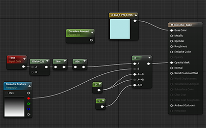
Et, voilà!
It’s not very impressive looking yet, but, that is the basic technique behind our effect. Let’s refine it even more, though. Before continuing on, if you want to try swapping in different images for Dissolve Texture to see how they change the dissolve effect, go ahead, just make sure to turn off sRGB for the textures. A lot of what goes into creating good effects is simple experimentation and time, so don’t be afraid to spend time trying out different things.
At this point, our basic dissolve material is working, so let’s connect the Dissolve Amount node to the If node and delete our Time, Abs, and Sine nodes, and the Divide node if you used one. Alternatively, you can leave the nodes in your graph for later use. As long as they’re not connected to the main graph, they won’t hurt anything. Switching to the parameter value will give us more precise control and let us preview the effect at any dissolve amount, which we’ll want as we move forward fine-tuning the look of the effect. Change the current value of the Dissolve Amount parameter to “0.5” so that our preview will show the object in a partially dissolved state.
Here’s the updated graph node for comparison:
Fixing a Problem
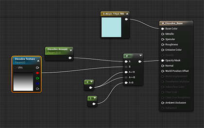
Before we continue, there’s one small issue that may not be obvious. When we have a Dissolve Amount of 0.0, any pixels that reference pure black parts of the Dissolve Texture will be transparent. We don’t want that, since 0.0 represents a completely undissolved state. We could fix this by connecting the 1 node to the A==B pin, but then we’d have the opposite problem — we’d have pixels represented by pure white parts of the texture not fully dissolving when Dissolve Amount was set to 1.0.
The way to handle this special case is with a second If node, this time comparing Dissolve Amount to 0. If Dissolve Amount is equal to 0 (or less than 0, but that shouldn’t happen), we’ll use 1, otherwise, we’ll use the amount from the previous node.
Right-click the graph node and type “If” to add a second If node. Connect Dissolve Amount to the A input node of the new If node. We could recycle the 0 constant node from before, but I usually create new ones to avoid a spaghetti-like mess of node connection wires. Hold down 1 and left-click the node graph to add a new constant node then connect it to the B pin.
Hold down 1 and left-click the node graph to create another constant scalar node. Use the Details inspector to change this one’s value to 1.0, then connect its output pin to the A==B pin and A<B pin of the new If node. Connect the first If node’s output pin to the B pin of the new If node, and then connect the output pin of the new If node to the Opacity Mask pin of the material.
Now your node graph should look like something like this:
Adding the Fringe
If you look closely at the disintegrate effect in the GIF at the beginning of this post (click the image to see an .mp4 version), you’ll notice that there’s a red or blue glowing fringe along the line of the disintegration, almost like the burning edge of smoldering paper. We’ll add that next, and we’ll add it in such a way that we’ll be able to specify the color, intensity, and size of the fringe using material parameters.
What we need to do is use the Emissive Color pin of our material to specify which parts of the object should glow. We need to drive that pin off the same image texture that we use for the dissolve, only the color emission needs to be slightly “ahead” of the opacity mask time-wise, otherwise it will be masked out and we won’t be able to see the glow. To do that, all we have to do is add a small amount to the Dissolve Amount parameter and use the increment amount to drive the Emissive Color pin.
Except, if Dissolve Amount is 0.0, then we don’t want any glowing fringe at all. If we don’t account for 0.0 as a special case, we’ll have a small amount of glowing happening on completely undissolved objects. To handle that special case, we’ll simply check the value of Dissolve Amount with another If node and will only create the fringe if it’s greater than zero.
Click and drag from the Dissolve Amount pin. When you let go of the mouse button, you’ll get a pop-up menu. Type “Add” and select an Add node. If the Add node isn’t selected, click it to select it, and in the Details panel, set Const B to 0.01. This will add a tiny amount to our Dissolve Amount parameter. Later, we can adjust this value until we like the effect. I just picked 0.01 for starters because it seemed like a good, small increment. Remember, experimentation is key, so don’t be afraid to try different values to see how it impacts the look of the effect.
From the Dissolve Amount node, click and drag out again. This time, when prompted, type “If” and create another If node. We’re going to use this node to make sure that we don’t increment Dissolve Amount if it’s 0. Hold down the 1 key and click to create a constant node with a value of 0. Connect that new 0 node to the B pin, the A==B pin, and the A<B pin of the new If node. By doing this, we’re saying, “if Dissolve Amount is zero, output zero”. But what if it’s not zero? then we want to use the incremented value, so connect the output pin of the Add node to the A>=B pin.
Next, we’ll use the result of this new If node to drive the color for the Emissive Color pin of our material. Right click in the node graph and type “If” to create yet another If node. Connect the output of the second If node we created to the A pin of the new node. Connect the Dissolve Texture to pin B. Just like with our opacity mask, we’re comparing the incremented Dissolve Amount value to the texture so the texture can drive the fringe3.
Instead of 0s and 1s this time, we want the output of our node to be a color. For places where we don’t want any light emitted, we want to output pure black, and for places where we want light to emit, we want a brighter color. Press the “3” key on your keyboard and left click the graph to add another Vector Constant node. It should default to black, but if it doesn’t, use the Details inspector to change it to black. Connect this black node to the A==B and A<B pins of the third If node.
Press the “3” key on your keyboard again and left-click the graph to create another Vector Constant node. Pick a nice bright color for this one using the Details inspector. I used a bright red. Connect this bright color node to the remaining A>=B pin of the newest If node.
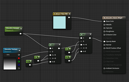
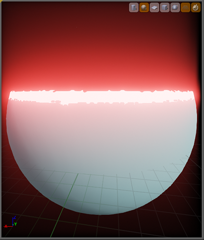
If we connect the output pin of this If node to the Emissive Color node of our material, we’ll get a fringe, however, it will be kind of a pathetic fringe. We want it to be bright, like it’s burning or electrified. To do that, we need to amplify the color so the component values are above 1.0. Click and drag from the If node’s output pin and let go of the mouse button. When prompted, press “*” to create a Multiply node. In the Const B field of the Multiply node, put “50.0”. This will boost the fringe and make it look like it’s really glowing. Again, feel free to tweak the value to your liking.
Your material preview should now look something like this:
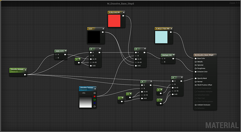
Your graph node should look like this:
Making it Configurable
We’ve got a pretty nice result now. Let’s add a few parameters so we can tweak the effect without changing the node graph any more.
First, let’s put in a parameter to control the size of the fringe. In our material, the fringe amount is represented by a very small number (0.01) which represents how far ahead in time, as a percentage, the fringe is. That’s not a very easy concept to explain. To create something more intuitive, let’s accept a positive number that defaults to 1.0. Increasing the parameter above 1.0 will make it larger, decreasing it will make it smaller. To do that, all we have to do is divide the input by 100 and feed it into the Add node.
Right-click in the node graph and select Scalar Parameter. When prompted for a name, type “Fringe Size” and assign it to the group Dissolve. Give it a default value of “1.0”. Drag out from this parameter’s output pin and let go of the mouse button. When prompted, press the “/” key to create a Divide node. In the Const B field, type “100”. Now, connect the output pin of the Divide node to the B pin of the Add node. We now have a parameter that will let us adjust the relative size of the fringe dynamically.
Next, right-click on the bright color node you created and select Convert to Parameter. Give it a name of “Fringe Color” and a group of Dissolve. Now, we can adjust the color of the fringe dynamically.
One last parameter to go. Right-click the node graph and create another Scalar Parameter. Call this one “Fringe Glow Intensity” and put it in the Dissolve group. Give it a default value of “50.0”. Connect the output pin of this new parameter to the B pin of the Multiply node that connects to the Emissive Color pin of your material.
Select the Dissolve Amount parameter and set its default value back to “0.0”. Save your material and close the Material editor window.
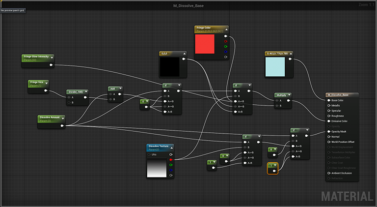
And that’s it. Your final material should look something like this:
Let’s try out, shall we?
Creating a Static Material Instance
In order to dissolve our material, we’ll need to create a Dynamic Material Instance at runtime, but we can base that Dynamic Material Instance off of a Static Material Instance. Doing that will let us configure the look of our material in the material editor rather than having to do it in Blueprint or code, which can be tedious.
Right-click on M_Dissolve_Base in the Content Browser and select Create Material Instance. You can leave the name at the default M_Dissolve_Base_Inst. When you start creating additional material instances, you’ll probably want to give them more meaningful names, but this is fine for testing. Double-click M_Dissolve_Base_Inst to open the Material Instance Editor.
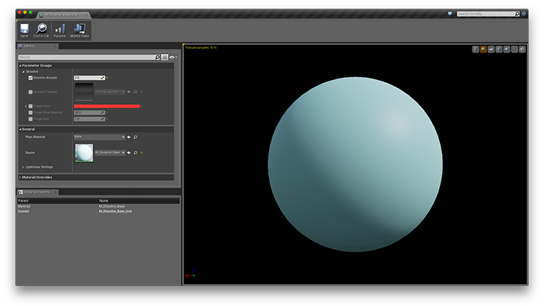
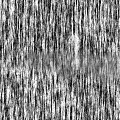
Go ahead and override any values you want. If you want a more interesting noise texture, you can try this one:
After you’ve got the parameter values set to something that looks good save it and close the Material Instance Editor. You can preview by overriding the Dissolve Amount parameter, but just remember to set it back to 0.0 and uncheck the override box when you’re done.
Creating an Actor to Dissolve
We need to set the Dissolve Amount parameter over time from Blueprint or C++ to create the illusion of disintegration. To keep things simple, we’re going to do it from Blueprint. We’ll create a simple Actor Blueprint with a cube static mesh component and then add logic that will dissolve the cube.
From the Content Browser, select Create, then select Blueprint from the list that drops down.
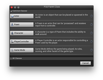
You’ll be prompted for a parent class. Select the Actor button, and when the new blueprint appears in the Content Browser, name it “BadBox_BP” (you don’t think we’d disintegrate a good box, do you?). Once you’ve changed the name, double-click it to open the Blueprint Editor. If you’re not already on the Components tab, navigate to it.
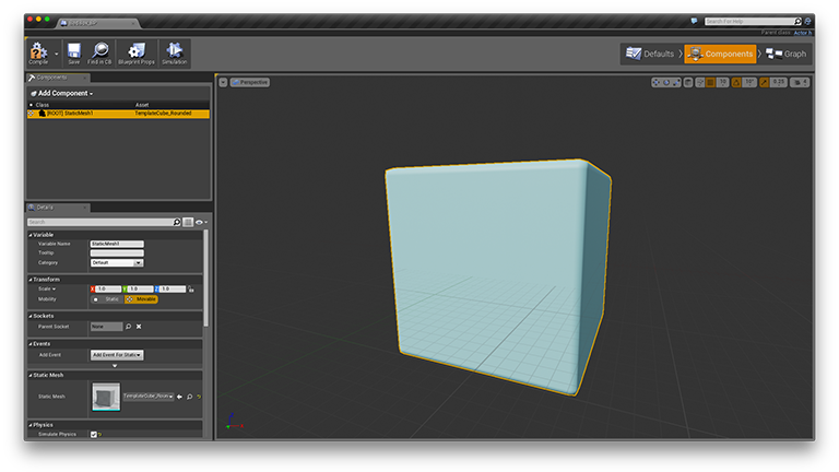
In the Components inspector in the upper left, click Add Component and select Static Mesh. In the Details panel, find the Static Mesh chooser, and select TemplateCube_Rounded (or any other static mesh you want to destroy).
Scroll down a little further to the Rendering section, and press the plus button next to Materials to create a new Material slot. Use the material selector to select M_Dissolve_Base_Inst.
In the Details inspector, look for a section called Physics and check Simulate Physics.
Creating the Dynamic Material and Dissolving
In the Blueprint Editor, switch to the Graph tab. We need to create a Dynamic Material Instance that will allow us to change the Dissolve Amount value over time.
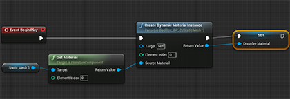
Right-click in the graph node and type “Event Begin Play”, find the item in the list with that name, and hit return. That will add a red node to the graph. This node will fire once when the level starts. In the My Blueprint inspector on the left side, you should see a reference to a component called StaticMesh1. Drag that out onto the node graph and, when prompted, select Get to add a reference to the cube static mesh to your graph.
When writing a real app, don’t use names like “StaticMesh1”. You’ll regret it later when you have dozens of them and don’t know which represents what.
Click the output pin of the Static Mesh 1 node and then let go of the mouse button. Type “Get Material” and hit return. Drag out from the Exec pin of the Event Begin Play node (the white hollow arrow on the right side of the node) and type “Create Dynamic”. From the list, select Create Dynamic Material Instance (StaticMesh1) and hit return. Now, connect the Return Value node of the Get Material node to the Source Material node of Create Dynamic Material Instance node.
That’s all there is to creating a dynamic material instance whose values can be changed at runtime. To make things easier on ourselves, let’s store a reference to this material instance in a variable. We could retrieve the material from the material slot of Static Mesh 1 every time we wanted to use it, but it’s easier and creates a simpler node graph if we just store a reference in a variable.
In the My Blueprint inspector, hit the Variable button to add a new variable. Give the new variable a name of “DissolveMaterial” and a Variable Type of MaterialInstanceDynamic.
Drag DissolveMaterial out from the My Blueprint inspector to the graph and select Set when prompted. Connect the Exec out pin of the Create Dynamic Material Instance node to the Exec in pin of the newly created Set node. Also, connect the Return Value pin of the Create Dynamic Material Instance node to the DissolveMaterial pin of the Set node.
Your graph node should now look like this:
Dissolving the Cube
Our cube is set up with a dynamic material, but we need to actually dissolve it. Let’s make it dissolve when the cube takes damage, which will let us test our material by shooting boxes.
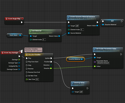
Right-click again in the graph node and type “Event Any Damage”, select Event Any Damage, and hit return. This node will fire any time the cube takes damage. From here, we just have to increment the Dissolve Amount parameter of the dynamic material over time to make it dissolve.
Click and drag from the Exec out pin on the new node and type “Timeline”. Scroll down the list until you find Add Timeline… and select it. Timelines let you change a value over time. This will let us increment the dissolve amount over time without implementing the Tick event and doing it manually.
When the new node appears, its name will become editable. Call it “DissolveTimeline”. Double-click it to open the Timeline Editor.
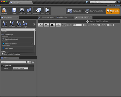
In the upper middle of the Timeline Editor, there’s a field called Length that has defaulted to a value of “5”. Change it to “.75” so that our dissolve happens in three quarters of a second. To the right of that, look for a button labelled ƒ+. Click it to create a new “float track”. A float track is used to change the value of a floating point number over time. When prompted for a name, type “Dissolve”
Right-click in the timeline and select Add Key. Set the Time of the new key to 0.0 and the value also to 0.0. This key represents the start point of our timeline, which is 0, or completely undissolved.
Right-click the timeline again and select Add Key again. This time, set the Time to .75 and the Value to 1.0. Now, we have a timeline that increases a value from 0.0 to 1.0 linearly over three quarters of a second. We can use the output of this track for our dissolve. Save the timeline, and close its tab to get back to the main event graph. A new output pin will have appeared on your timeline called “Dissolve”.
Drag the DissolveMaterial variable from the My Blueprint inspector on the left side of the window to the event graph to the right of DissolveTimeline. When prompted, select Get to add DissolveMaterial as a node. Drag out from the pin on this new node and let go of the button. Type “Set Scalar” and select Set Scalar Parameter Value. Connect the Update pin of the DissolveTimeline to the Exec in pin of the new node.
On the Set Scalar Parameter Value node, there’s a pin called “Parameter Name”. We won’t be connecting this to anything, but next to the pin, there’s a text field. Type “Dissolve Amount” into that field. This tells it which scalar parameter we want to change.
Finally, drag from the Dissolve output pin of DissolveTimeline to the Value input pin of Set Scalar Parameter Value.
We’re almost done. The only thing left to do in this blueprint is to destroy the cube after it’s done dissolving. Drag out from the Finished pin of DissolveTimeline and type “DestroyActor”. This will destroy our cube after the timeline has finished running
Drag out from the Update pin of DissolveTimeline and let go of the mouse button. Type “Set Scalar” and select Set Scalar Parameter Value. This node will let us change Dissolve Amount on our dynamic material instance.
We’re now done with this blueprint. It should look something like this:
Go ahead and save it and close the window. We’re practically done, but it won’t actually dissolve yet. Right now, there’s no way to cause damage to the cube. The default projectile in the First Person template adds force to objects it hits, but does not cause damage to them. We need to modify the projectile’s blueprint in order to make it cause damage to things it hits. If we don’t, the Event Any Damage node will never fire, and our dissolve will never kick off.
Inflicting Damage
In the Content Browser, navigate to the Blueprints folder and double-click MyProjectile. Navigate to the Graph tab if you’re not already there, and you should see that there’s already some Blueprint there:
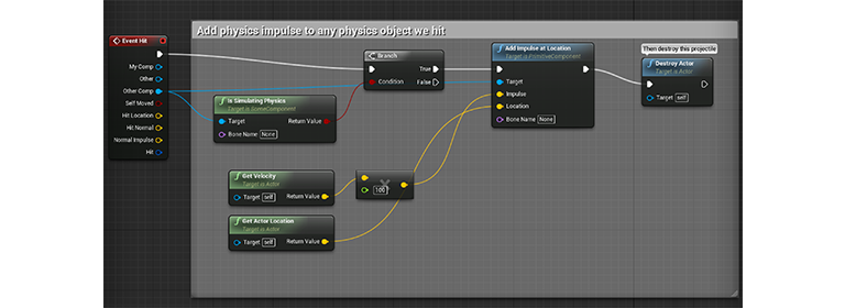
All we have to do is add another node to inflict damage. Find the Destroy Actor node and drag out from its Exec output pin. When you let go of the mouse, type “Apply Damage”. Way back on the right side of the graph, look for an output node called “Other”. That represents the object we hit. Connect that pin to the Damaged Actor input pin on the node we just added. Now, put a non-zero value in Base Damage text field and save it. The graph should look like this:
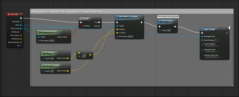
It may seem odd that the projectile applies damage after it has been destroyed. You can put the Apply Damage node before the Destroy Actor node if you prefer, but it works just fine. When you call Destroy Actor, the object is marked as destroyed, but doesn’t actually get removed until later in the game loop, so it will work just fine like this.
Give it a Try
All that’s left now is to drag out one or more copies of your BadBlock_BP to the level. You might want to remove the existing cubes from the template to avoid confusion. Once you’ve got a few bad blocks to shoot, hit Build and then Play and shoot those bad blocks to make them disintegrate.
That’s the whole process. There are many more things you can do to expand on this basic concept, such as adding a secondary color fringe, but even with just this material we’ve created here, we can create a whole slew of different effects by changing the texture that drives the dissolve as well as the other material parameters. We could even change the other parameters at runtime, perhaps changing the fringe from white to red as it dissolves. Combine dissolves with particle systems to add smoke, fire, electricity, or blood splashes, and you’ll be able to get some surprisingly convincing results.
The one thing you really have to watch out for is that objects tend to look hollow with this technique… because they are. For objects that are being disintegrated, consider modeling some internal geometry as a second static mesh and having that dissolve a fraction of a second after the outer mesh. That’s how the skeletal dissolve at the top of the article was achieved. You could take the same idea even further, having multiple layers of dissolving parts, maybe internal organs and blood vessels as separate dissolves fractions of a second apart, or using different dissolve patterns.